After months of development, it is possible to finally see the Scene Editor in action! In this devlog, we’ll walk through the core editing workflow, explore the Viewport panel, and dive into how 3D graphics are rendered under the hood. We’ll also cover the graphical features implemented so far and how they tie together.
Let’s jump in.
Scene Creation & Structure
 and associated files in a list view (right). A context menu is available for quick resource creation.")
Figure 1: Scene Editor with Resource Browser. The Resource Browser is open, displaying the project folder structure in a tree view (left) and associated files in a list view (right). A context menu is available for quick resource creation.
Once a project is initialized, the Resource Browser can be opened by clicking the Resources button in the bottom-left corner of the workspace.
The browser displays a tree view of the project structure.
Navigate to the Resources folder. This is where all project assets live. Right-click inside it and create a new folder named Scenes.
Inside Scenes, right-click again and select: Create Resource → Scene
This generates two related resources:
Scene Resource (the main container)
Scene Layer Resource (a subdivision of the scene)
Double-clicking the Scene Resource opens it in the editor. By default, it contains two layers:
Runtime Layer – A volatile container for objects spawned dynamically during execution. It cannot be saved to disk.
Main Layer – The primary editable layer added during scene creation. This is where artists and designers place static content and save changes to disk.
You can create multiple scene layers to split your scene into logical, potentially asynchronously loaded containers. For example:
A Lights layer
A City_Block_A layer
A Dynamic_Objects layer
This modular approach keeps scenes manageable and improves loading performance.
Mesh Creation & Import
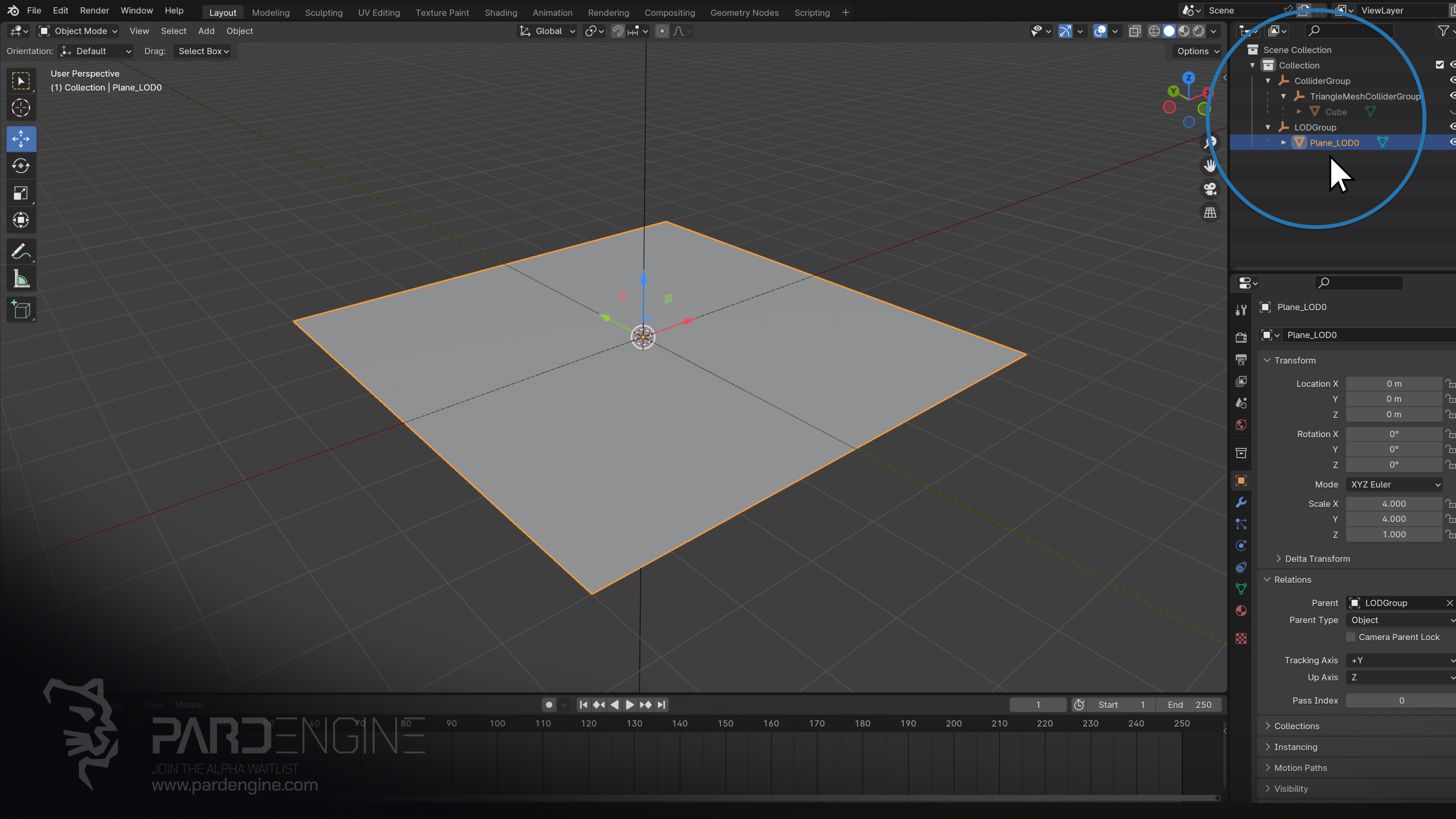
Figure 2: Blender Interface. The viewport displays a floor mesh, while the scene hierarchy (tree structure) is shown in the top-right panel.
To populate our scene, we’ll start with a simple floor mesh created in Blender.
Back in the Resource Browser, right-click in the list view and select: Import Resource
In the Open File Dialog that appears, we can choose from supported formats like .fbx, .obj, and more. For this workflow, we’ll import an FBX file exported from Blender.
Important: For early Pard Engine builds, meshes imported from external 3D authoring software must conform to a predefined hierarchy. This layout is mandatory for accurate collider and level-of-detail (LOD) configuration. A step-by-step guide will be included in the first tutorial series.
Once imported, the engine generates a .peres (Pard Engine RESource) file (the one shown in the Resource Browser). This file stores the source mesh data in a particular intermediate format. From this, the engine compiles an optimized binary (containing vertex/index buffers, GPU-ready data etc.) and caches it in the project’s Cache folder for fast runtime access.
Drag & Drop & The Component System
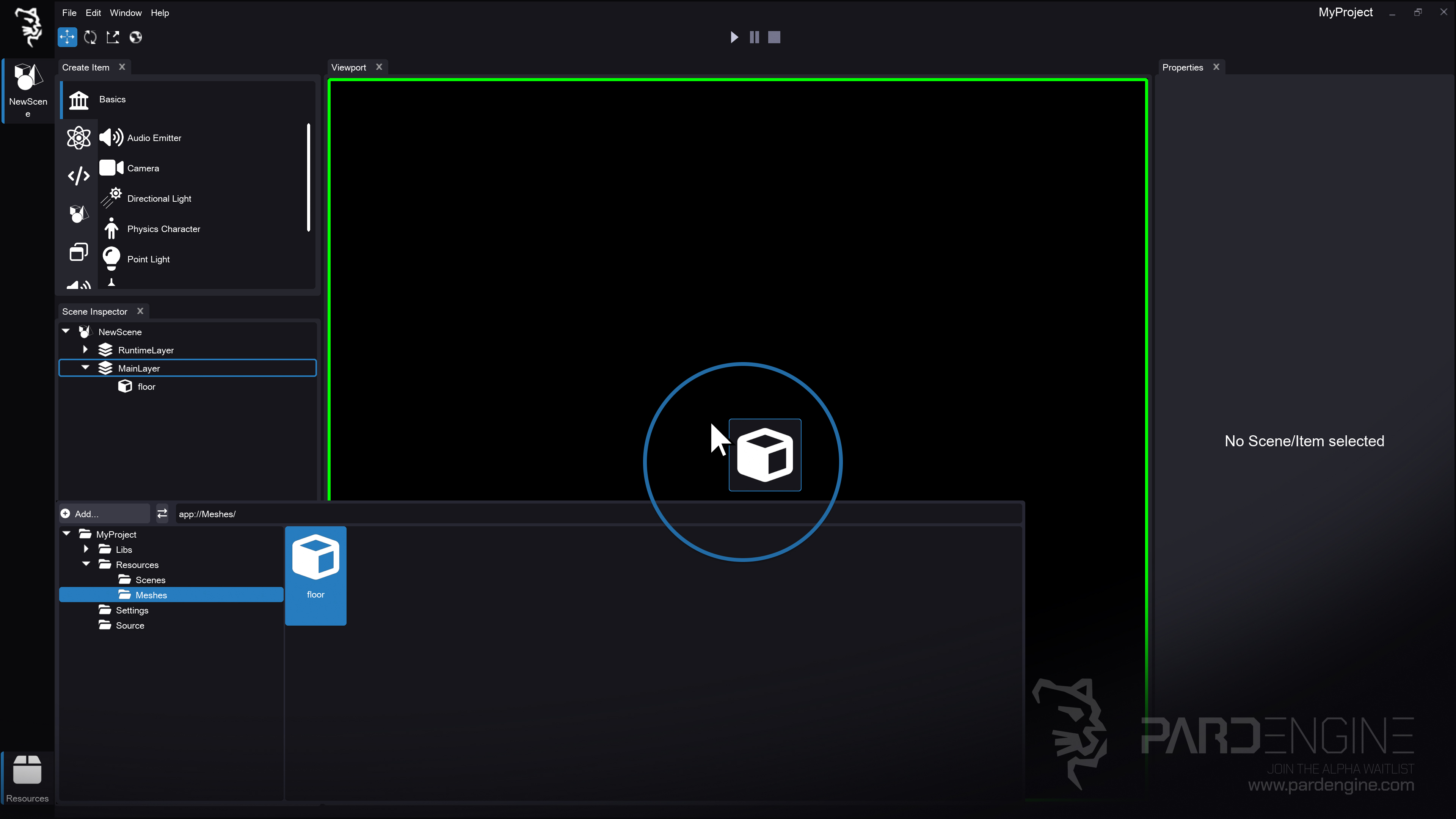
Figure 3: Drag-and-Drop Asset Import. The floor mesh is dragged from the Resource Browser and dropped directly into the viewport panel.
With the floor mesh in the browser, drag it directly into the Viewport inside the Main Layer.
The editor automatically:
Creates a new Item named after the imported mesh
Populates the Scene Inspector panel
Displays its Properties in the Properties panel
As discussed in previous devlogs, Pard Engine uses a hierarchical component system. The dropped mesh becomes a StaticMeshComponent attached to the item as the Root Component of the hierarchy, with the imported resource bound as its source.
Nothing will render in the viewport yet. The engine requires lighting and material data to compute visibility. Let’s fix that.
Adding Lights to the Scene
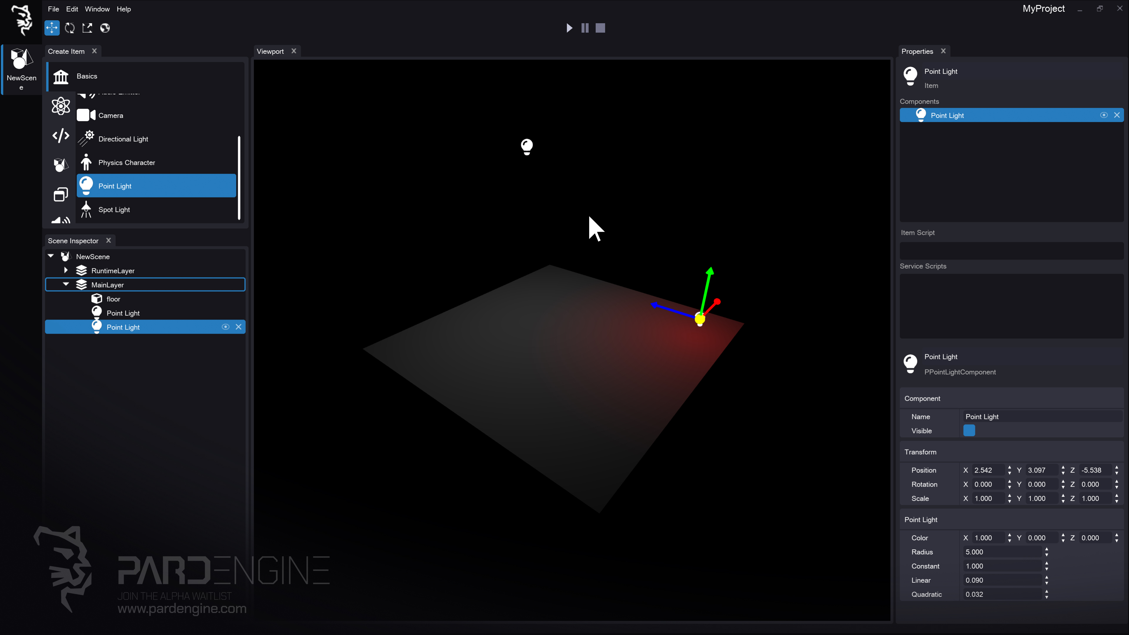
Figure 4: Adding Illumination. Two point lights are placed in the main scene layer, illuminating the floor mesh and making it visible in the viewport.
Open the Create Item panel, which lists all registered components. Thanks to Pard Engine’s metadata and reflection system, components are automatically grouped into tabs based on their type.
Under the Graphics tab, you’ll find lighting components. Drag a Point Light into the viewport.
Suddenly, the floor mesh becomes visible. Add another point light to see how multiple light sources interact.
Transform Gizmo Controller
Once items are placed, we can manipulate them using the Transform Gizmo:
Translate Mode (default): Move objects along X (red), Y (green), or Z (blue) axes
Rotate Mode: Rotate objects using the same colored axis handles
Scale Mode: Uniform or axis-aligned scaling
We can switch between Global and Local gizmo orientations:
Global: Fixed to world axes, regardless of object rotation
Local: Aligns to the object’s current transform orientation
Applying Materials
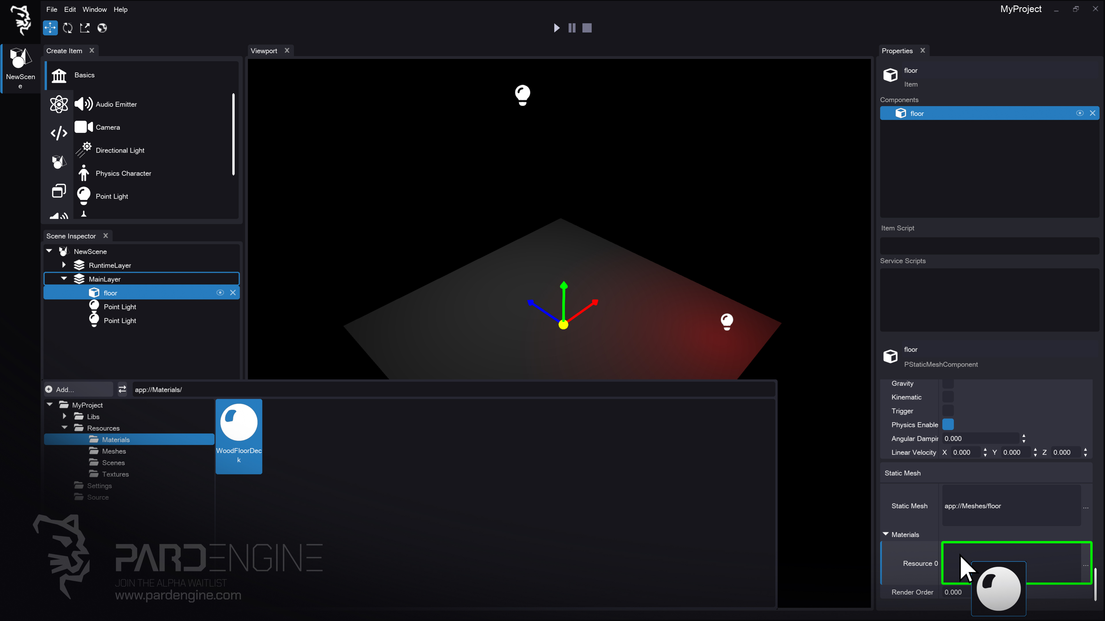
Figure 5: Applying Materials. The WoodFloorDeck material is dragged from the Resource Browser and assigned to the floor mesh’s material slot in the Properties panel.
With lighting in place, let’s add surface detail. Select the floor mesh, navigate to the Properties Panel, and expand the Materials group.
Drag and drop the WoodFloorDeck material from the Resource Browser onto the slot. The default gray material is instantly replaced with a PBR-ready material.
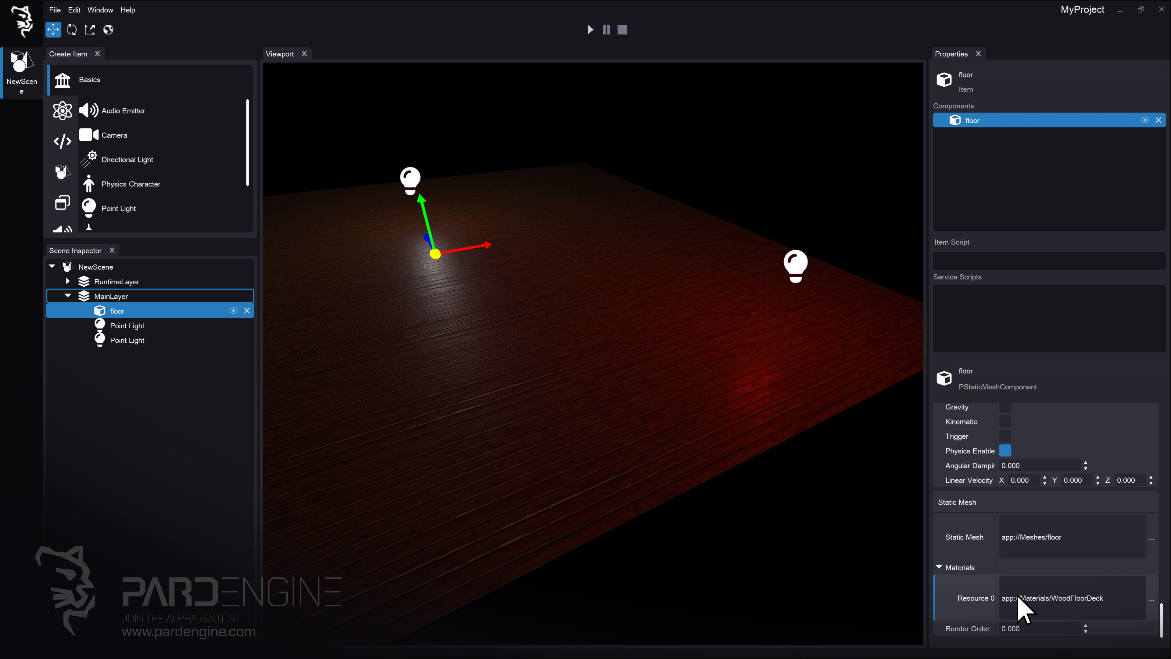
Figure 6: Material Preview. The floor mesh now displays the WoodFloorDeck PBR material, showcasing realistic surface detail and lighting response. (Assets: Poly Haven)
Under the Hood: Graphics Engine
To power visual fidelity, Pard Engine ships with a custom Graphics Engine designed around:
Physically Based Rendering (PBR)
Dynamic Lighting (Direct, Environment)
Customizable Rendering Pipelines (Deferred, Forward, etc.)
Render Hardware Interface (RHI) Abstraction
Direct Lighting
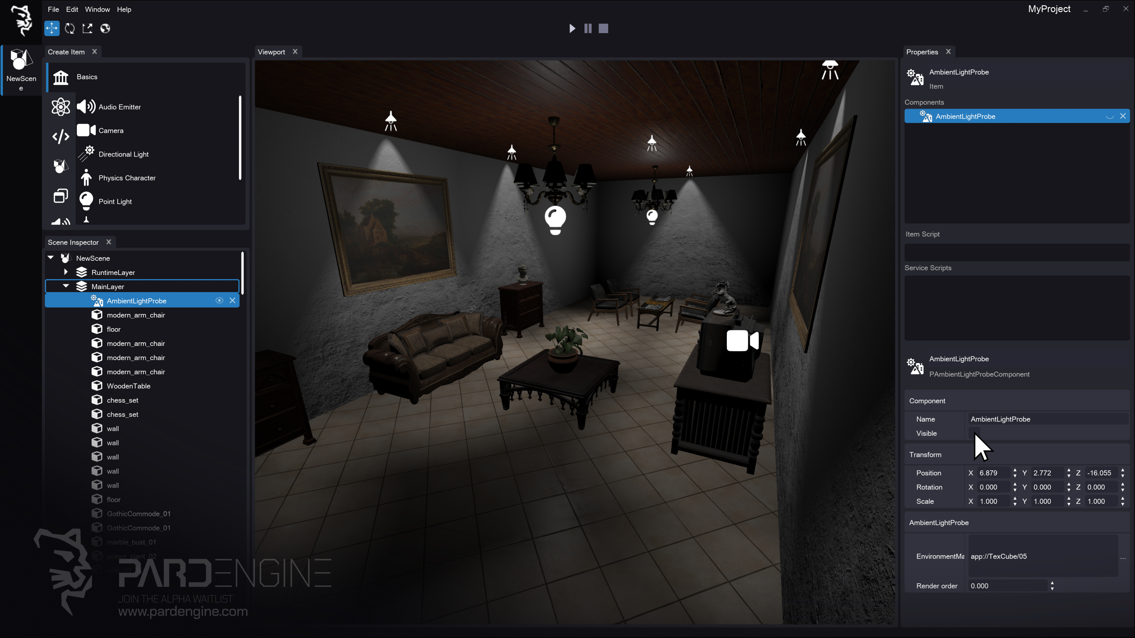
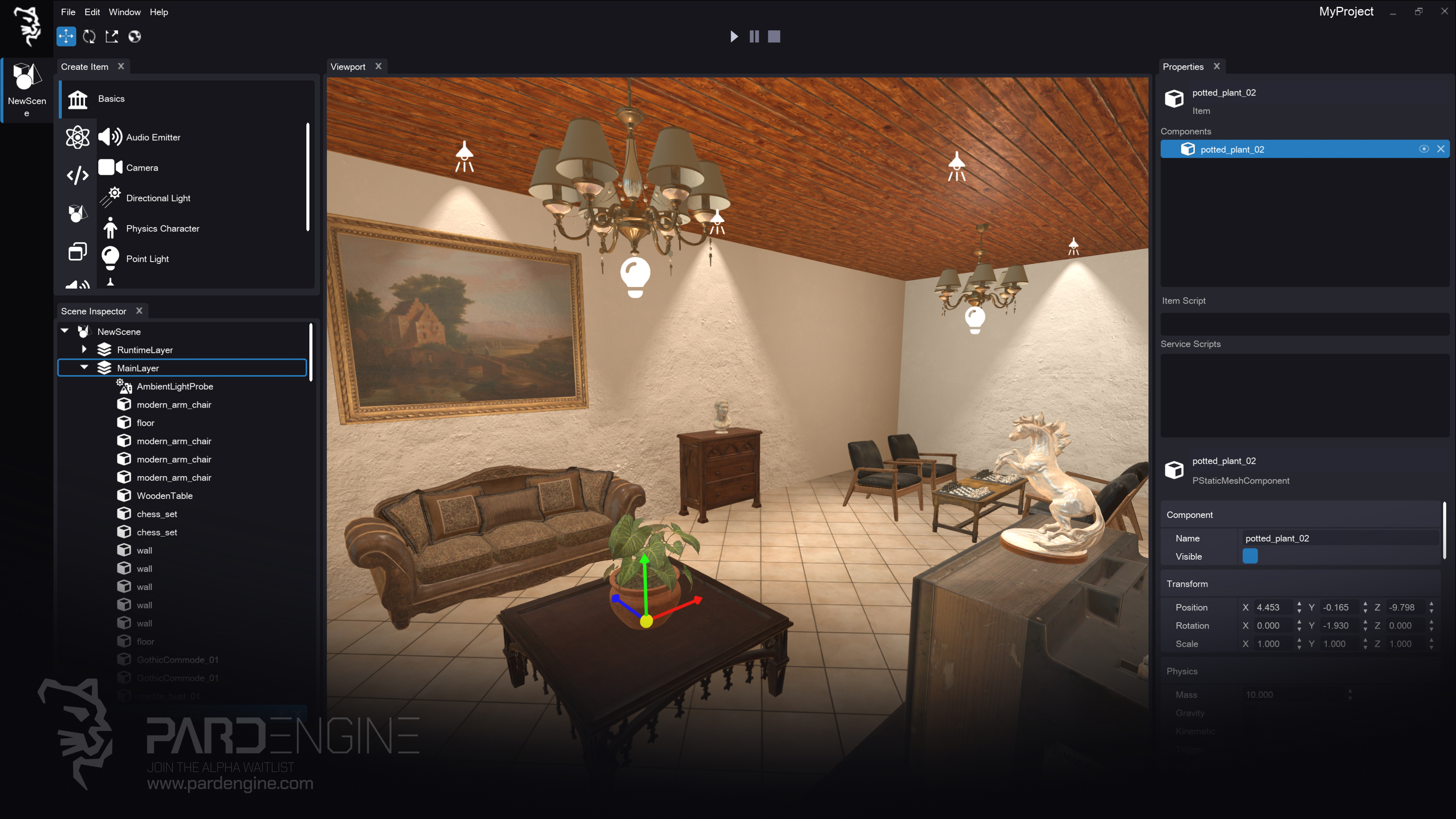
Figure 7: Direct Lighting. The living room scene is rendered in the viewport using direct lighting only. (Assets: Poly Haven)
Pard Engine supports Direct Lighting by providing three core direct light types:
Directional Light casts perfectly parallel rays that hit every surface uniformly, regardless of position. Best for sunlight, overcast skies, and large-scale outdoor environments.
Point Light radiates equally in all directions from a single location, gradually fading with distance. Ideal for lamps, candles, and realistic indoor ambient fill.
Spot Light projects a controlled cone of light with a sharp center and soft outer edge, allowing precise coverage. Perfect for flashlights, stage fixtures, or highlighting specific objects.
Using the workflow above, we assembled a simple living room scene composed of direct light sources.
Physically Based Rendering (PBR)
Physically Based Rendering (PBR) simulates how light interacts with materials using physically based models and material parameters such as:
Metallic: Determines whether a material behaves as a metal or a non-metal (dielectric).
Roughness: Controls the microscopic surface irregularities that affect how light is scattered and reflected.
Tuning these values produces realistic, predictable shading across varied lighting conditions.
Environment Lighting & HDRI
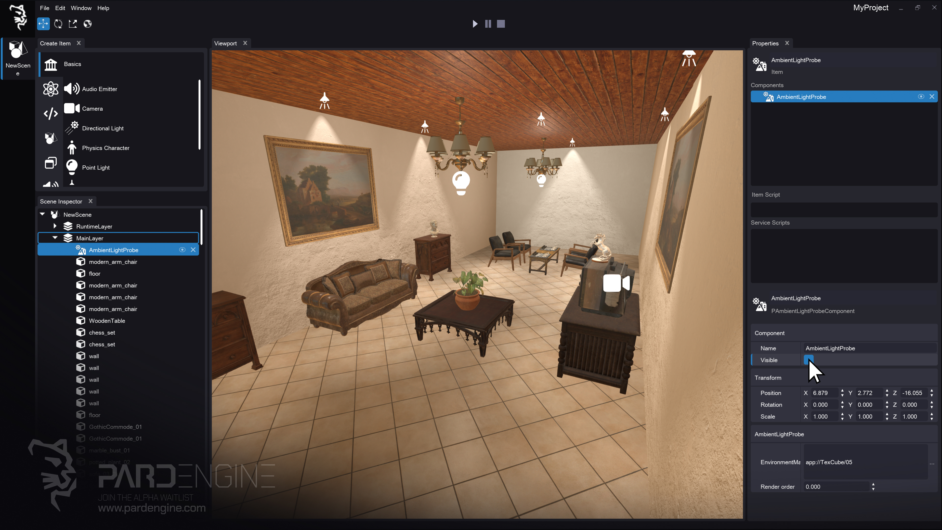
Figure 8: Environment Lighting. The same living room scene now includes environment lighting, applied via an AmbientLightProbe component and an HDRI environment texture. (Assets: Poly Haven)
In early builds, environment lighting will be provided via an Ambient Light Probe component. This uses an HDRI (High Dynamic Range Image) panorama that stores 360° environmental light data.
When set, the Ambient Light Probe component provides low-frequency environment lighting information to the scene, contributing to indirect illumination and subtle ambient color variation, which can enhance perceived realism. Simply drag the probe into the scene and assign the HDRI texture in the Properties panel.
Graphics RHI (Render Hardware Interface)
Pard Engine’s Graphics Engine is built atop a Render Hardware Interface (RHI), an abstraction layer that provides a unified API between rendering code and low-level graphics APIs such as Direct3D, Vulkan, and Metal. It hides platform-specific details, allowing the engine to execute rendering commands consistently across different platforms.
Current & Roadmap Support:
Direct3D 12 (Primary Renderer)
Direct3D 11 (Planned for Legacy compatibility)
Vulkan / Metal (Planned for broader platform coverage)
D3D12 was chosen as the foundation for its low-level control, explicit multi-threading, and architectural clarity. It provides the performance headroom and modern feature set required to build a forward-looking rendering pipeline. Legacy and integrated GPU support (Direct3D 11) will be added in the future to ensure broad compatibility.
What’s Next?
In the next devlog, we’ll dive deep into the Material Editor, covering HLSL Shader Code , PBR channel mapping, and custom material logic.
If you have feature requests, technical questions, or feedback on the Scene Editor workflow, join the discussion in our Discord community channels here:
Thank you for being part of the Pard Engine journey!
We’re closing in on our Alpha version release, and your interest fuels every line of code we write.
How you can help us grow:
Support us on Patreon: Every contribution powers our development, no matter the amount.
Patreon LinkJoin our Discord: Chat with devs, share ideas, and get early updates.
Discord LinkReady to spread the word?
Share this article anywhere you like using the buttons in the share bar.
We can’t wait to dive into the next devlog with you!